CS 111Scribe Notes for 5/16/05by Marina Cholakyan, Sepehr Sahba, Omid Behzadian, and David PhungI/O Systems
Operating System manages and controls I/O operations and I/O devices. The
examples of I/O hardware are storage devices (disk), transmission devices
(network cards, modems) and human-interface devices (screen, keyboard, and
mouse). To understand better how OS controls I/O devices let’s take a look
at Figure1 (Machine Hardware Layout) and understand how the devices are
attached. Devices such as the disk can communicate with the CPU, and vice
versa, through I/O ports, which are manipulated by instructions like
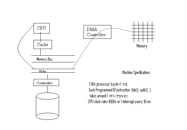 The figure has been decorated with important machine parameters that influence the performance of different methods for interacting with devices. These numbers may vary on your machine, but their relationships are realistic.
To summarize:
Our goal is to figure out the efficiency & latency characteristics of different ways of interacting with I/O devices. Let’s say we want to get 40 bytes from some device. In this lecture we'll discuss several different ways: polling, interrupts, and direct memory access (DMA) (both with interrupts and with polling). POLLING
In a polling design, the OS simply checks from time to time if a device has
completed a request. To read 40 bytes from a device with polling, the CPU
would:
Let’s see how much is Latency -- 50 us + (0 ms) * 1/2 + (10 ms) * 1/2 ~= 5 ms. Why? Well, remember that in this variant of polling, we don't check the device until the next clock interrupt happens. How long until the next clock interrupt? Call this time t. Then the latency is simply the expected value of t. So assume that requests arrive according to a uniform random distribution, meaning that a request is equally likely to arrive at any time: 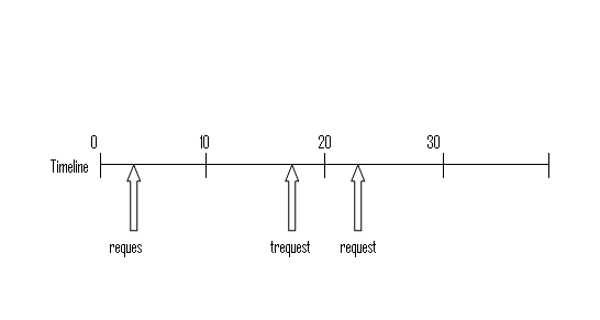 This means that t, the expected distance between a request and the next clock interrupt, is also distributed uniformly at random, between 0 ms (when the request arrives immediately before an interrupt) and 10 ms (when the request arrives immediately after an interrupt). Statistics tells us that the expected value of a uniformly-distributed random variable is simply halfway between its extremes: in this case, 5 ms. This is a huge latency: 5 million cycles! How can we reduce this latency? Well, we need to check more often. But the most extreme way to check more often is busy waiting. This is inefficient, obviously, because while checking if device is ready or not the CPU doesn't do any other work. So instead, it would be great if devices could notify CPU when it’s ready, instead of checking on device all the time. Interrupts do this! INTERRUPT-DRIVEN I/O
When the device is ready the device controller raises an interrupt telling CPU to transmit to the interrupt handler and handler clears the interrupt by servicing the device.
To set up interrupt-driven I/O we need: Now we will calculate the overhead, throughput and latency for interrupt-driven I/O. Overhead: 5 us (PIO) + 5 us (interrupt in step 3) + 50 us (PIO) ~= 60 us. Note that the device think time (step 2) is not part of the overhead. Throughput: Again, this is determined by CPU overhead, so throughput is 1/overhead = 16,000 operations/sec. Latency -- Just 65 us (the overhead + the 5 us think time)! Now it’s not bounded by clock interrupt time, but by how long it actually took to perform the operation. Let’s compare POLLING to INTERRUPT.
The advantage mostly gained is because of the latency, Interrupts have far less latency then Polling. Although it seems like interrupts are a better choice, but still there might be scheduling difficulties when there are many interrupts LIVELOCKWhen CPU receives interrupt it transfers control to interrupt handler, in other words Interrupts have Absolute Priority over the application process! There is preemption when interrupts occur. If many interrupts keep coming (say that they are packets arriving on a network card), they would take an absolute priority and would create a situation called LIVELOCK, where the computer does more & more work, but the Throughput equals to zero. 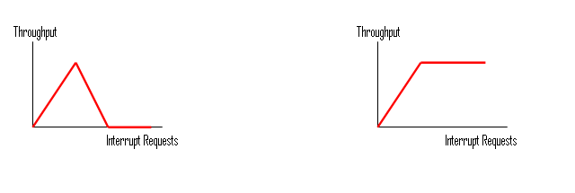 The first graphic is the LIVELOCK situation, where after a certain point, interrupt processing steals time from request processing. Eventually, the system spends all its time processing new requests in the interrupt handler, and the CPU is too busy to actually finish processing any requests. That means it does no useful work! The second graphic is something we would prefer to have, where the PC still would have throughput. DMA (DIRECT MEMROY ACCESS)If we take a look back at the overhead results that we computed for Polling and Interrupt-Driven systems we can easily determine that the major part of overhead (CPU busy time) is taking place at the actual read operation. For a device that does large transfers, such as disk, it seems wasteful to use an expensive general-purpose processor to watch status bits and to enter the data to the device using Programmed I/O (PIO) operations one byte at a time. We can avoid burdening the main CPU with PIO by offloading some this work to special purpose processor called Direct-Memory-Access (DMA) controller. Usually the structure for DMA is a wait-free-queue (such as circular array) called DMA Ring. Each element of this DMA Ring structure contains one request that needs to be processed. Here is how the structure looks like: 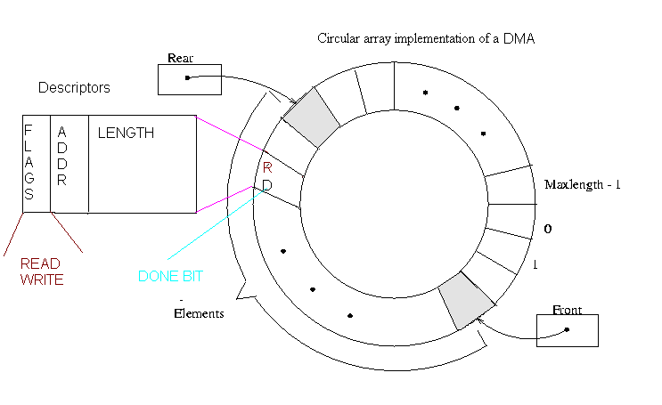 To initiate a DMA transfer, the host writes a DMA command block. The block contains a pointer to the source of a transfer, a pointer to the destination of the transfer, and the length of the bytes to be transferred. The CPU writes the address of this command block to the DMA controller (each element of the Ring). Once the CPU requests, the “request” bit will be set for that specific block. After DMA controller detects a request (in our case a read operation), DMA controller starts data transfers, which gives the CPU an opportunity to perform other tasks. Once the DMA reads all the data, only one interrupt is generated per block and CPU will be notified that the data is available at the buffer (DMA sets the DONE bit to notify the CPU). Now let us investigate overhead, throughput, and latency of the Polling method using above DMA structure. DMA+POLLING
Overhead -- 0 Ms 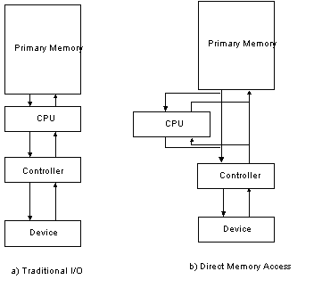
Throughput: DMA+INTERRUPT
If you remember for interrupt driven approach we calculated 60 Ms overhead: FILE SYSTEMS
The file system may be the most important visible aspect of an operating system. It provides the mechanism for on-line storage of and access to both data and programs of the operating system. File systems provide: Hierarchical DirectoriesA hierarchical directory structure is used to organize the files that exist on a hard disk. This logical tree is used on almost every file system because of the intuitive way it arranges files and the power it gives the user to create meaningful organization schemes for files. The root directory is special because it, alone of all directories on the file system, has no parent. There is only one root directory on each file system. 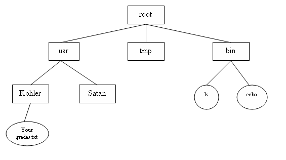
In general, file systems provides an abstraction layer between hardware and
software applications. This allows us to bypass all the lower level
operations and details. This is am example of such an abstraction.
Low Level Characteristics of DiskCheap and Persistent Storage 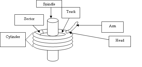 A disk consists of a number of magnetic platters revolving around a central spindle. All the platters are the same size. Data can usually be stored on either surface of each platter. There is one head per surface; this is the object that reads data off the disk. Heads are moved to the right position on the disk using the arm. All the heads move as one; independently moving arms would be hard to engineer. Data is stored on the disk in concentric circles, so that the head can read contiguous chunks of data while the platters rotate (the heads don't have to move). These circles are called tracks. Each track is broken into discrete units called sectors. All modern disks store 512 bytes per sector. A cylinder consists of all the tracks, one per surface, that can be read by the different heads when the arm is in one position. How long does it take to read data off a disk? This can be broken into three components.
To summarize:
- 1 head and arm per surface
Example – Seagate 73.4 GB SCSI Lesson: Seeks Suck. Much of modern OS file system design tries to avoid the costs of seeks, through various caching strategies and clever file system layout. The basic intuition is to design the file system so that locality of reference implies proximity on disk. This means that, if two pieces of data are usually accessed closely in time relative to one another (locality of reference), then they are located close to one another on the physical disk too, to minimize seek time and rotational latency (proximity on disk).
What operating OS support for disk?
- Fixed size allocation unit for disk space - In practice, 4KB = page size = 8 Sectors UNIX’s FILE SYSTEM STRUCTURESSuperblockThe superblock contains the set of basic information that the computer needs to know about the disk. Some of this information includes block size, disk size, location of the root directory and some bookkeeping information. Block size and disk size are important for the operating system to know how to interpret the sectors on the disk as well as ensuring space requirements. The location of the root directory, which is simply a block pointer, is important because if we know this location we can find all other files in our directory since UNIX is a hierarchical file system. This information contained in the superblock is crucial for successfully mounting the file system, therefore this information needs to be kept in a convenient location. UNIX stores the superblock in a fixed location on disk, more specifically it stores it in block number one. UNIX also maintains multiple superblocks, replicated throughout several locations on the disk, so that if one becomes corrupted, one of the other superblocks can still be found and used to mount the file system. Directory and File BlocksThere are two types of files in a UNIX file system. The first is a file representing a directory, commonly referred to as a directory block, and the second is a structure representing actual user data, commonly referred to as a file block. Directory blocks contain pairs of file names and file pointers. The file pointers are actually inode numbers that correspond to the file names. These inode numbers can reference either another directory or file since UNIX directories can contain either one. File blocks contain the actual block pointers to user data. InodesEach entry in the UNIX file system including file blocks, directory blocks, links and special files have an entry in a special index. Each entry in this index is called and inode, which is short for index node. Each of these nodes is indexed by a single number called the index number. Inodes most importantly contain block pointers to whatever they are referencing. Inodes also contain the type of thing it represents (i.e. file, directory, link, etc). These two pieces of information alone allow one to access any file in the file system. For example suppose one wanted to access a file in /usr/bin/ls. The first step would be to look up the root inode, which can be found in the superblock described earlier. The operating system then reads its directory block to find the entry for /usr, reads /usr 's inode, reads its directory block to find /usr/bin, reads /usr/bin's inode, reads its directory block to find /usr/bin/ls, reads /usr/bin/ls 's inode, and then reads the data from its file block Inodes also contain other information such as size, a set of permissions bits, owner and group information, the time last modified, and other types of similar file attributes. Free Block BitmapThe free block bitmap is a contiguous amount of free space on disk, where each bit represents the status of each block of data in the file system. The bit is set to one if the corresponding block is free and zero if it is not free. The free block bitmap starts in the second block, directly after the superblock, and continues on to however many blocks are needed to represent all the blocks in the file system. This bitmap ensures that a given disk block is used for only one purpose at a time. Therefore before allocating a block to a file, the operating system must check to see if the corresponding block is free (i.e. set the corresponding bit to 1). Similarly when we delete a file, the operating system should free the corresponding block(s) (i.e. reset the corresponding bit to 0). CS111 Operating Systems Principles, UCLA. Eddie Kohler. May 25, 2005. |